

Wind Energy Generator Step-Up (GSU) Transformers
With the advent of renewable energy, the number of wind and solar farms has been on the rise, and economical benefits were originally found in the use of pad mount transformers to step up the voltage as produced by the turbine generator. However, the rate of failure of these transformers in service has led to the investigation of the total cost of ownership in trying to balance the low cost distribution design pad mount transformers with its cost of premature failures to custom designed ISUs that take into consideration the onerous applications in Wind power characteristics. This article looks at identified failure modes and mitigation that we have adopted to improve robustness.
The reliability, or lack thereof, of pad mount transformers used as Wind Turbine Generator Step-Up (WTGSU) transformers has been well documented. Broadly, this failure is exhibited in one of three ways:
- HV winding failures – this is a class of failures primarily caused by:
- Over-voltage due to fault conditions and load rejection, as well as transient over-voltages from switching operations, can lead to winding failure if not mitigated.
- Increased mechanical and electrical stress due to the loading cycles of WTGSU.
- Increased risk of partial discharge due to gassing. (See 2 below).
- Gassing – this is a class of failures due to elevated gas generation of:
- Hydrogen gas – An early sign of gassing, as a result of five-legged wound core construction that was predominantly used in pad mount transformer designs.
- Combustible (hydrocarbon) gases – due to the hot spots formation and localized heating. (See 3 below).
- Heating failures – this class of failures due to general and localized heating are attributable to:
- Overloading due to sizing variations of transformers to wind turbines, especially during periods of high wind speeds.
- Harmonics seen by the transformer winding during turbine start up and operation, resulting in additional eddy and stray losses are a lot higher than expected in a distribution transformer application.
- Increased risks of hot spots due to gassing.
The occurrence of a factor listed above may not directly result in the failure of the transformer. However, there is considerable interrelationship between the factors, and the occurrence of a factor could lead to the manifestation of another factor, and so on, until eventually one or more factors are substantive enough to result in the failure of the transformer.
As a manufacturer of custom transformers, we have applied design considerations to cater to each of the potential issues faced by WTGSU application. Among these are:
- Core and coil designs that have been modified in the following areas to mitigate the issues identified above.
- Three-limbed stacked cores eliminate the issue of hydrogen gases that were an issue with the five-limb wound cores.
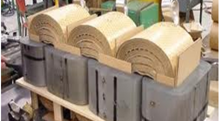
Five-limb wound core
Three-limb stacked core
-
- Core designs that allow for an additional 5% continuous overvoltage over what is prescribed by ANSI standards.
- The use of disc winding for the HV coil offers increased mechanical strength required for WTG application.
- The use of high temperature insulation in the winding hotspot region and other actions are taken to limit hotspot temperature.
- The use of electrostatic shields to complement the harmonics filtering by the wind turbine inverter and to prevent the transfer of voltage spikes from one winding to the other.
- Improved cooling to mitigate overheating and resultant combustible gas generation.
- Designed to the appropriate K-factor to account for the effect of harmonics.
- Winding construction with winding sticks and key spacers allow for more effective fluid circulation.
- Gradient and top oil rise are limited to cater for overload conditions during design.
- Ducts designed for optimal cooling oil flow.
These solutions, in addition to Virginia Transformer’s experience in the design and manufacturing of transformers, make our WT GSU transformers more robust and suitable for the application. This effort can be complemented by the customer and/or end-user who could:
- Adequately size the transformer to meet the design conditions of the wind turbine and site conditions.
- Implement a robust farm infrastructure which includes grounding transformers to minimize overvoltage in fault conditions.
- Closely monitor transformer performance for early detection of issues, which can be resolved before escalating to a dangerous failure. Monitoring should include but is not limited to liquid level, temperatures, and pressures, as well as periodic DGA of the oil.
CONCLUSION: We have been able to identify failure modes of pad mount transformers when used in WTGSU application and have used our experience with over several thousands of custom designs to develop design considerations to improve robustness of pad mount transformers when used in WT-GSU transformer application.
There are other economic considerations not covered in this article. Feel free to contact us at 540-345-9892 to assist in developing a robust specification or to answer your questions.